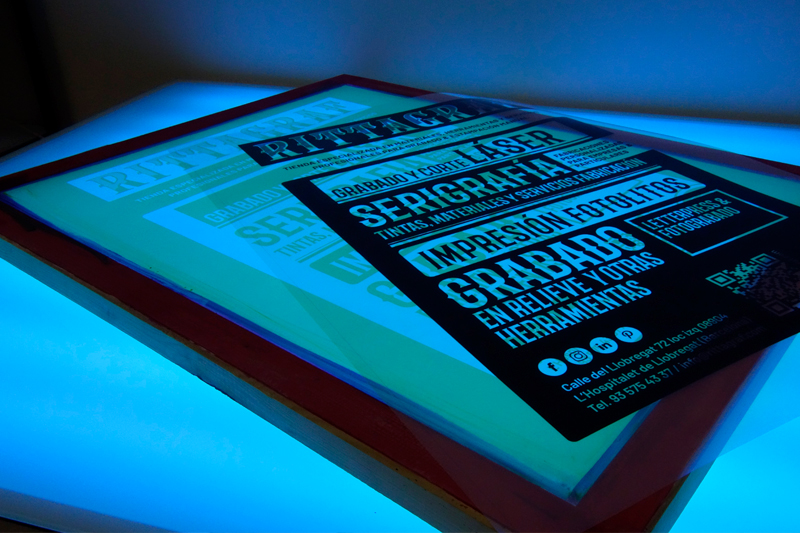
® Carlos Alguacil for Rittagraf
Many of you have asked for it, and here it is. We have retrieved and improved upon the classic tutorial written by our technician, Carlos Alguacil, back in 2016 when he led the technical content of Vostok Printing Shop. At that time, it was titled Un Tutorial esperado: Construir una caja de luz UV (An Expected Tutorial: Building a UV Light Box), and it helped many workshops and individuals take the first step in professionalizing their work. You won't find it on the internet anymore, but we have recovered and expanded upon it here. A significant part of this tutorial can also be found dissected in the book Triunfar Estampando (Triumph in Printing), edited by Gustavo Gili in 2018 under the original title Una mesa de luz UV: una herramienta multifunción (A UV Light Table: A Multifunctional Tool). So, paraphrasing the controversial phrase historically attributed to Fray Luis de León, dicebamus hesterna die or (as we said before):
What is a UV Light Table and What is it Used For?
A UV light box, Ultra Violet unite exposure light box/table, homemade exposure unit, UV light box, exposure table, or exposure unit are all different names used to describe the same tool. By definition, photomechanical processes require the use of an ultraviolet light exposure machine: a UV light box.
A UV light box has multiple uses and is highly beneficial for any printmaking workshop. With this type of box, we can expose screen printing frames, offset plates, photopolymer plates for photogravure, heliogravure, rubber stamps, or letterpress. We can even use it for other procedures close to photography, such as cyanotype, antotype or Van Dyke, among others.
There are various sources of illumination that produce the UV light waves required for these techniques, such as metal halide lamp, xenon lamp, high-pressure mercury lamp, mercury vapor lamp, super actinic fluorescent tube lamp, and UV LED light. The most common lighting technology used in professional exposure units are the metal halide lamp and the super actinic fluorescent lamp (commonly known as UV fluorescent tube)."
Type of UV light: UV fluorescent vs UV LED
Among all the lighting options that produce the UV light waves needed for these techniques, the most accessible options for building a homemade UV light box are UV fluorescent lights and UV LED strips.
In this case, we chose to build a UV light box with UV fluorescent lights instead of UV LED strips. The choice has a fairly logical explanation. You probably want to build a UV light box for screen printing, but you may also want it to be functional for other techniques. Screen printing emulsion manufacturers produce their emulsions based on the demand from their customers, and the vast majority still use metal-halide or UV fluorescent light exposure units. Just take a look at the technical data sheets from any manufacturer around the world. There, you will find application and exposure recommendations. It is possible that the future of the market will move towards the use of UV LED lights, but for this to work, LED light manufacturers and emulsion manufacturers need to align. At the moment, this is not happening.
Does this mean that I won't be able to do screen printing with a UV LED light box? No, certainly not. With a UV LED light box, you will also be able to make your screen printing screens and even use it for other techniques. But, although the use of UV LED lights is becoming more and more popular, we need to pay attention. It is important to know what technical characteristics the UV LED light we are using offers. Not all UV LED lights are suitable. It is easy to confuse technical concepts that can lead to disappointment in our work. An error in the construction of our box will end up making us doubt our emulsion, for example. And you may end up asking yourself, "why does it work for others but not for me?"
Building a UV Light Box Step by Step
In this tutorial, we will explain step by step how to build a UV light box with UV fluorescent lights.
As we have already mentioned, among all the lighting options, UV fluorescent lights combine the best features of each one: they are versatile, compatible with most manufacturers of photomechanical products and processes, relatively affordable, and currently easy to access the components.
Step 1: Choose the right UV fluorescent lights
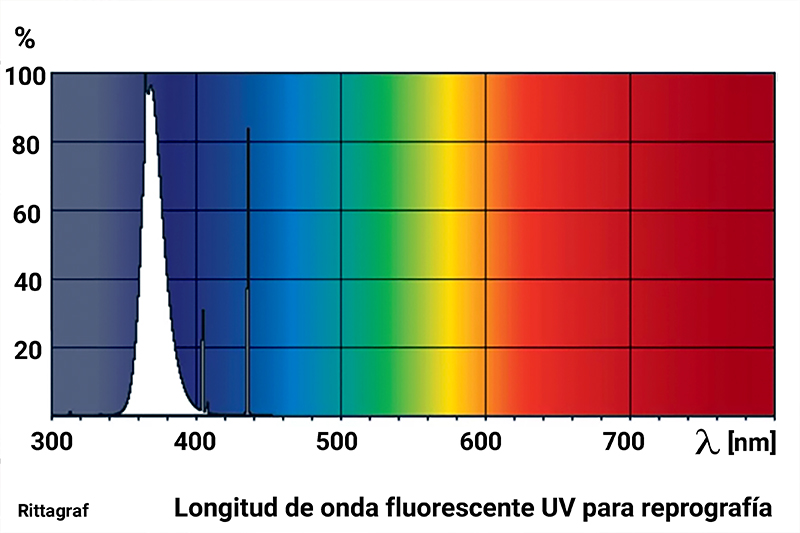
As mentioned earlier, in screen printing and other photomechanical techniques, materials are used that require light exposure to reactivate the substances they contain. For most of these materials, the required type of light is UV (ultraviolet) light. This type of light falls within a wavelength range of 10 nm to 480 nm (nanometers). Below 400 nm, this wavelength range begins to become invisible to the human eye, and around this wavelength, the light tends towards violet tones.
The most effective wavelength of light for our purposes is approximately between 350 and 400 nm. There may be variations depending on the material and technique we want to work with.
UV light bulbs attempt to simulate different ranges of ultraviolet light waves. Mostly, they reproduce some violet spectra that are visible to the human eye. There are many types of ultraviolet lights with diverse applications, and not all UV lights are suitable for our purposes, as not all produce the same range or power of light.
Classifications of UV light: The ultraviolet wavelength range is found within the spectrum of sunlight. Therefore, all the techniques we refer to can be carried out under the action of sunlight, but the process can be very uncontrolled.
Within the range of ultraviolet light rays, various subtypes are distinguished, and sometimes they are divided into categories. The most well-known are UVA (315 to 400 nm), UVB (280 to 315 nm), and UVC (100 to 280 nm), but there are many more divisions. Roughly, rays close to 400 nm are called short-wave and those approaching 10 nm would be extreme wave. Thus, we need to choose UV light bulbs of type A.
Step 2: Connection scheme for actinic fluorescents.
In our case, we have decided to make our light box with actinic fluorescents. Among other things, we think that actinic fluorescent is very accessible for everyone, does not require very large box depths, is relatively inexpensive, consumes less energy, and is suitable for all types of techniques that require ultraviolet light.
Conventional fluorescent lamps (white light) produce UV radiation but with a very short wavelength and, although it may work on some materials, we do not recommend it because it is inefficient. As we have already mentioned, we recommend using actinic fluorescent lights, or in other words: UV light.
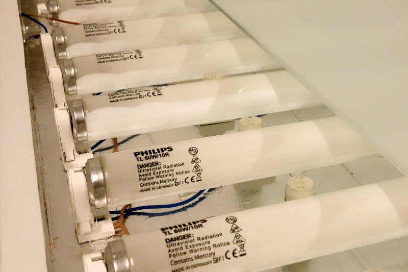
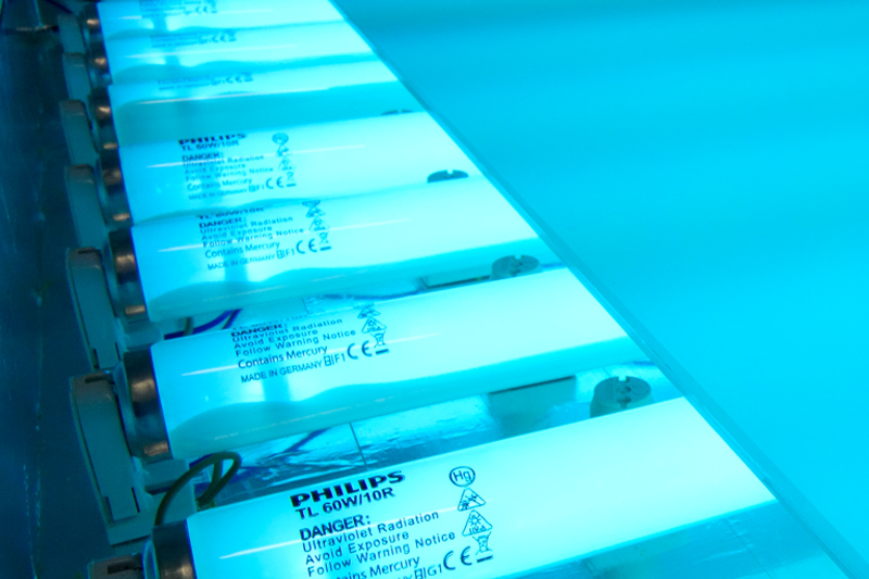
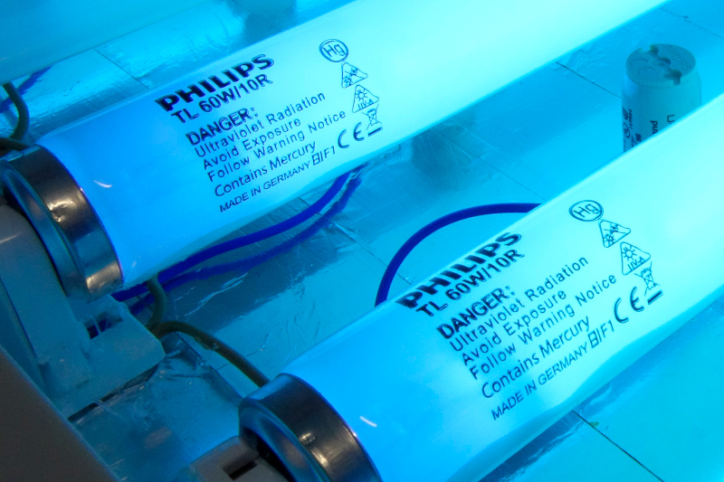
We can find them in different types and powers. We will be using the highest power ones. In our case, we have built a large box and used the actinic fluorescent TL 60W/101R reference from the Philips manufacturer (120 cm), specifically indicated for reprography and graphic arts. The BL TL-K 40W (60cm) or the BL TL-DK-36W/10 are also highly recommended for making smaller light boxes. The latter falls a little short for some techniques, and although it is not catalogued as a fluorescent special for reprography, it is still quite functional. We do not recommend anything below these power ratings for the intended use. The power and size correspondence of a UV fluorescent is different from that of common fluorescents.
At times, these fluorescents are also known as black light fluorescents. But we must be careful: commonly this name is for a type of UV light with a shorter wavelength (much less effective) and is usually used for decoration and to illuminate materials that are only visible with a very short wavelength of light, such as photoluminescent paints. You may have seen them placed in disco-pubs and nightclubs. Most lights called black lights are NOT effective for graphic arts; they will not give good results.
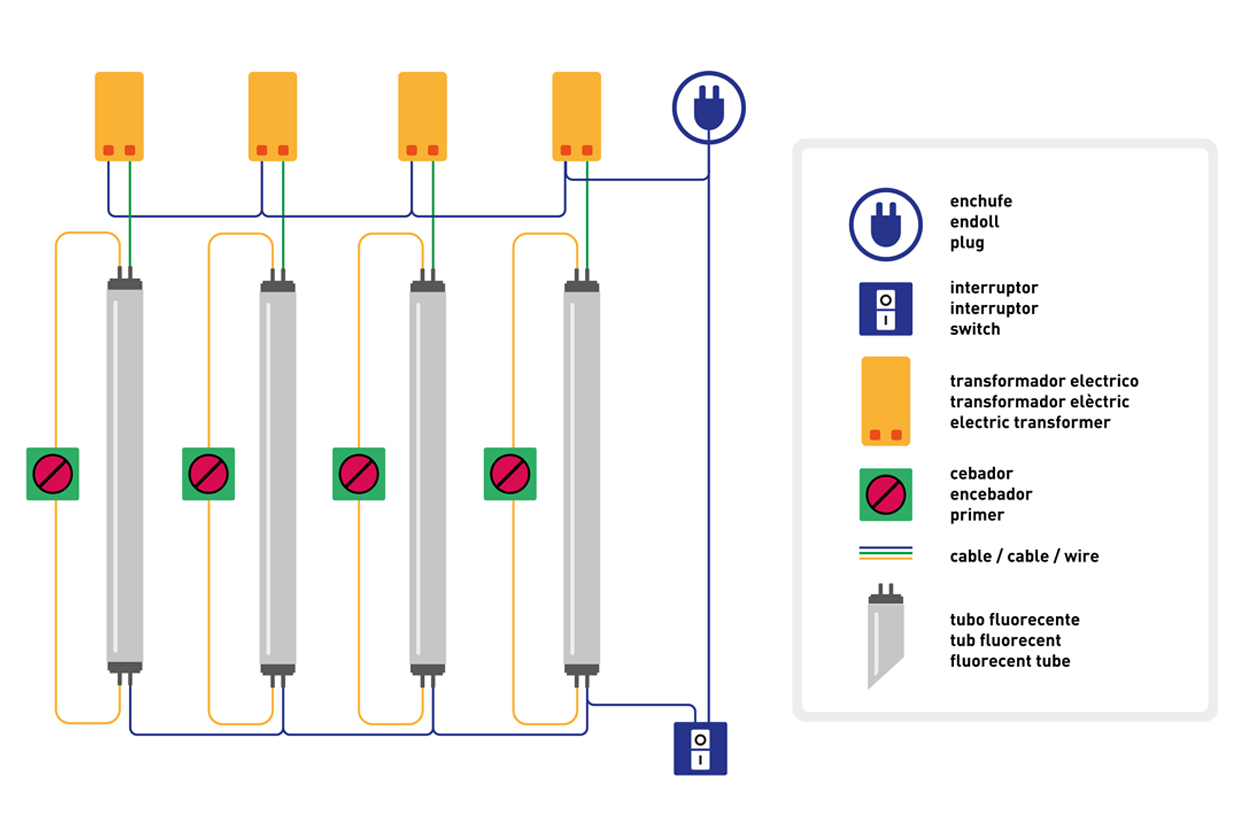
Creating a small scheme, even if it is not very technical, will help us understand the whole circuit and we can plan the necessary material in detail. Below, we have reproduced a very simple diagram of the electrical connections. The diagram has been simulated for 4 fluorescents, but the connections would be exactly the same for more quantities of fluorescents. We have used 10 actinic fluorescents of 60W (120 cm).
Important: Actinic fluorescents or UV light, despite being rated at 36W, 40W, or 60W, are shorter size than white household fluorescents of the same power rating. This is important to consider because it will influence the amount and direction in which we place them. It is worth checking before starting the construction of the light box.
Step 3: Materials required for assembly.
To build a UV lightbox, one of the first things to consider is the intended use. Our needs will determine the size of the box, its height, depth, the number of fluorescent lights required, and the materials needed.
In our case, we built a custom wooden box, but we could also use a drawer that meets our specific measurements and needs. To turn on, each fluorescent light will require a ballast and a starter. The illustration above shows how the connections should be made.
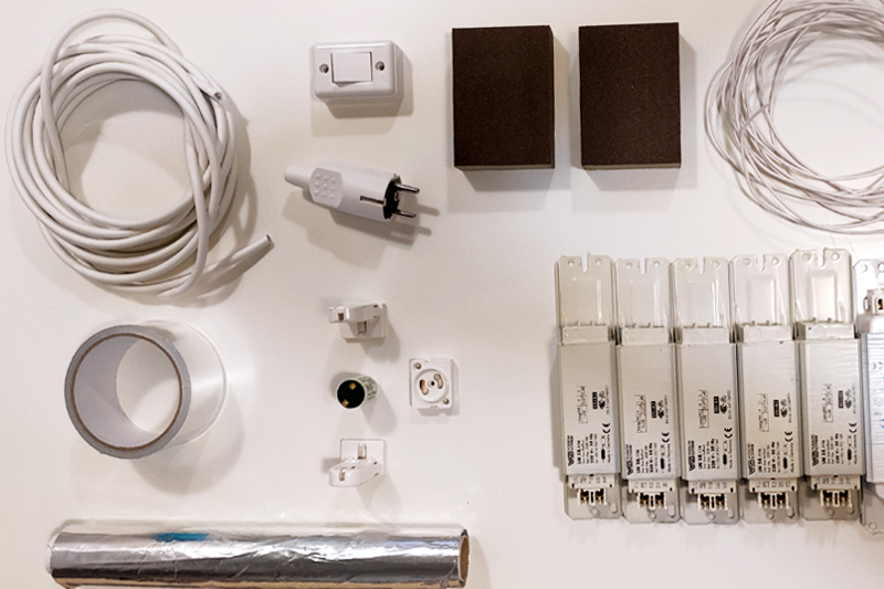
Before starting, we gather all the necessary materials:
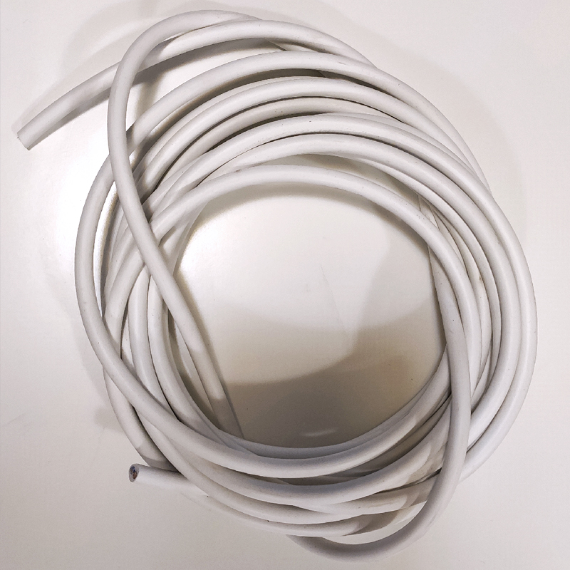
- Installation cable (it is important to know the required length. The diagram shows the connections).
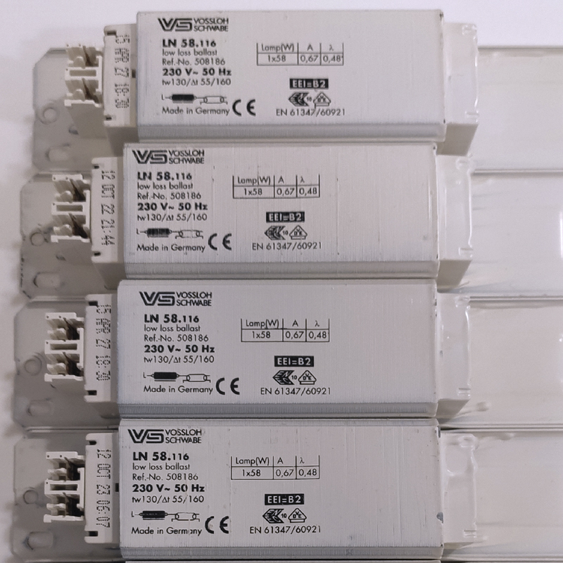
- One ballast for each UV fluorescent light.
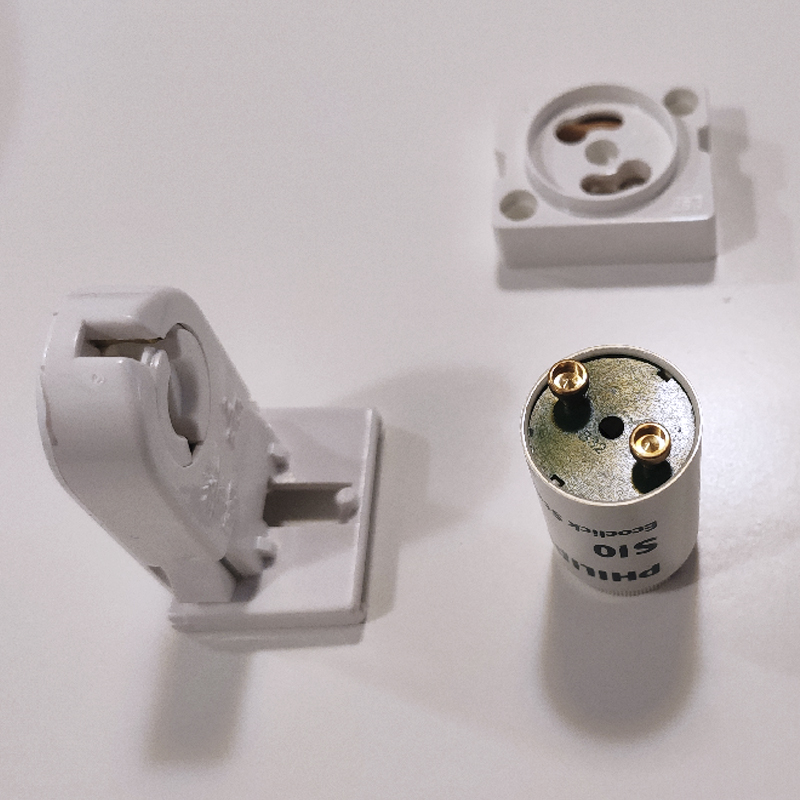
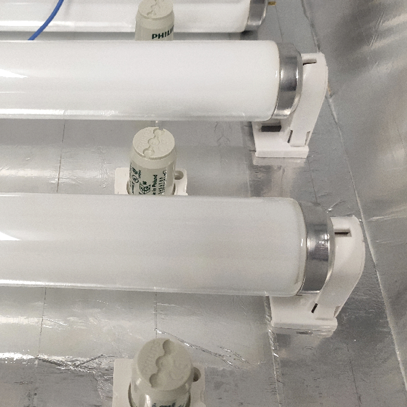
- One starter and a holder for each UV fluorescent light.
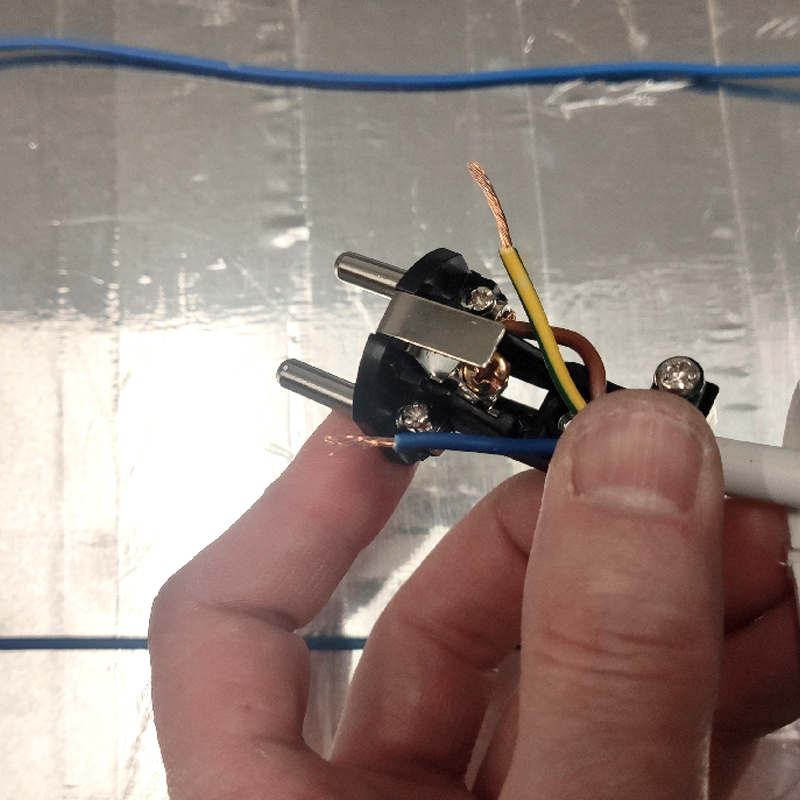
- One male plug.
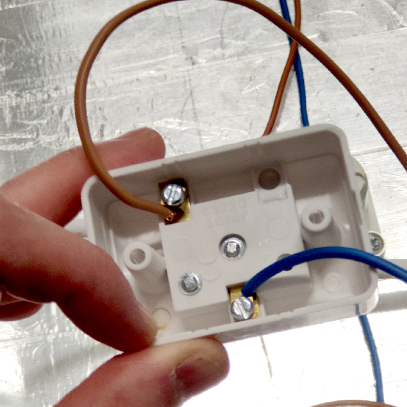
- One switch.
- As many actinic fluorescent lights and bases as desired. We installed 9 fluorescent lights of 120 cm in a box of 100x130 cm.
- Silver adhesive tape. Covering the box with a clear or reflective material will improve light performance and efficiency. The silver tape also helps to hide and secure cables.
- Frosted glass. The frosting causes better light diffusion. It is essential that the glass has no anti-UV treatment.
- Appropriate tools: screwdriver, glue and/or screws, scissors, etc.
- A timer (optional).

Step 4: Distribution and distance between fluorescent tubes
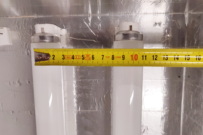
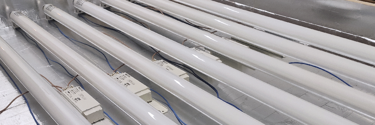
When assembling a light box of this type, it's very important to calculate a good distance between the UV fluorescent tubes. Depending on the height of the box, the fluorescent tubes should be more or less separated. We advise that the depth should not be less than 10 cm or greater than 25 cm. The box where we have built the exposure uv light box has a height of around 15 cm.
The separation between fluorescent tubes is essential. We need the light to reach the glass evenly. It is a matter of balancing the height of the fluorescent tube to the glass and the distance between them. When the light reaches the glass, the diffusion of light must cross and not leave any space on the surface with less light power. If the fluorescent tubes are too far apart from each other, or the depth of the glass to the base is very small, stripes and defects in the matrix that we are exposing will appear.
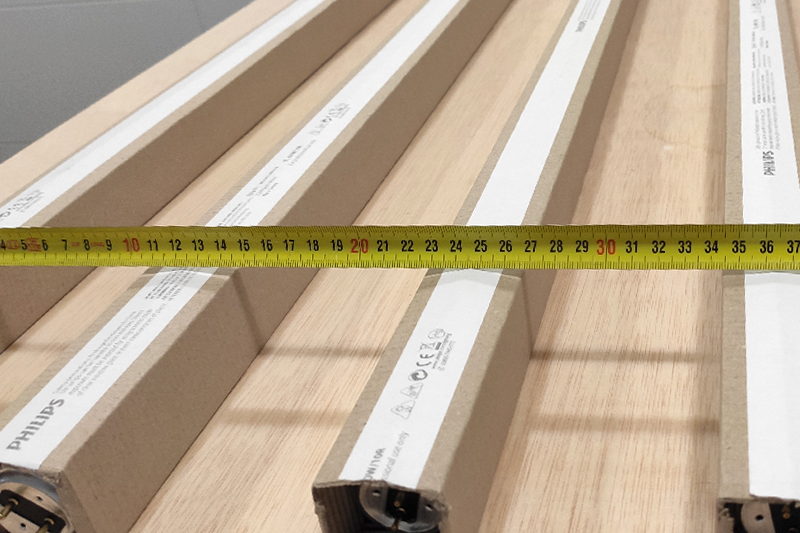
Here, we have measured the total surface of the box and, taking into account the height of the glass, we have separated the fluorescent tubes between 10 and 12 cm. This distance is counted from the center of the base of the fluorescent tube (not from the outer walls of the fluorescent tube). It should be noted that we can find this type of fluorescent tube in various thicknesses (depending on the brand and series), so we calculate the distance from the center of the base of the fluorescent tube.
For some techniques, such as photogravure or photopolymer materials, it is advisable to have the plate very close to the light source. These details can determine the characteristics of the size, distances, and depth of our ultra violet light box.
Step 5: Organize and Arrange the Elements
Once we have all the materials, we begin by covering our box with silver tape. This will help to better reflect the light, maximizing the power of the actinic fluorescent bulbs. While not essential, it will help improve the performance of our light box. If it is not possible to cover it, it is advisable to at least paint it white.
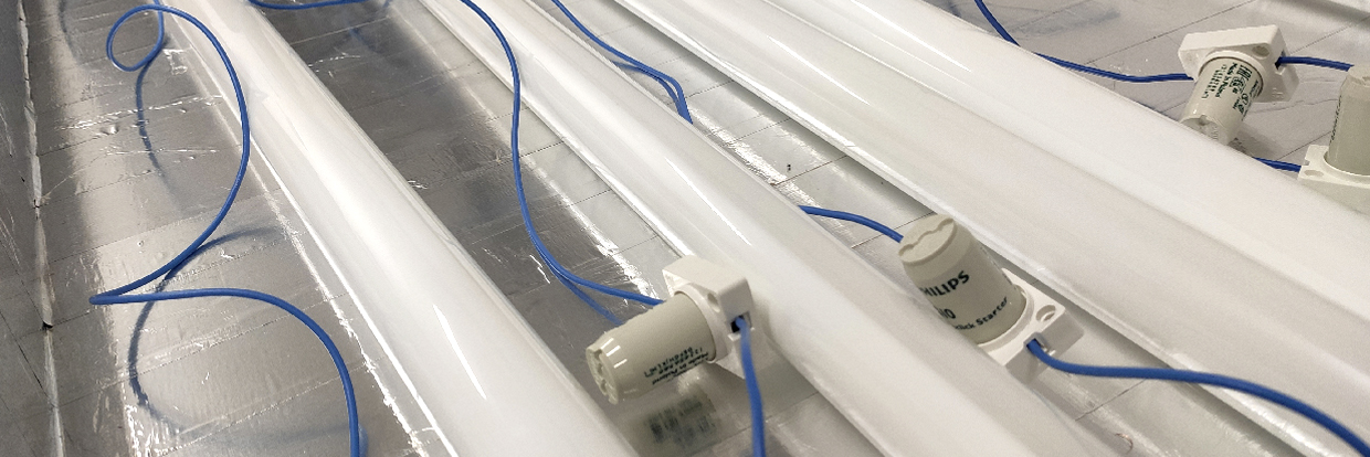
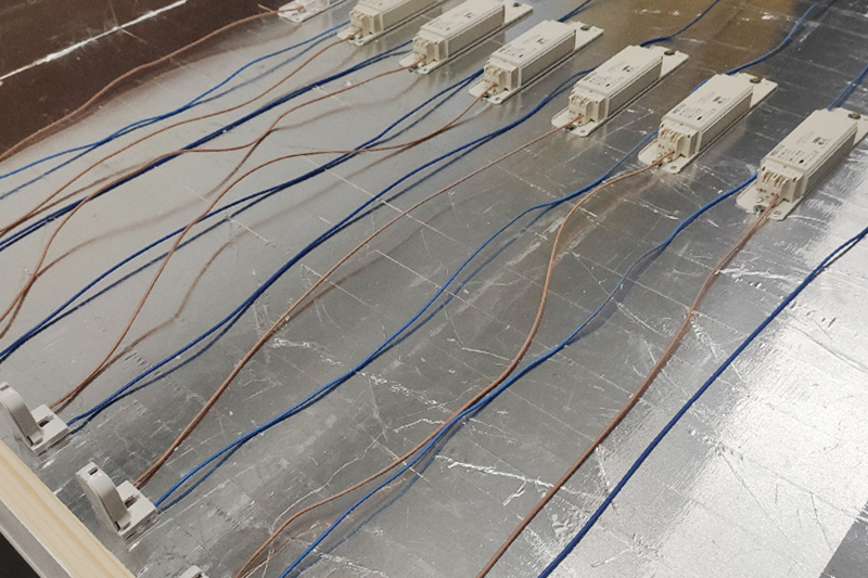
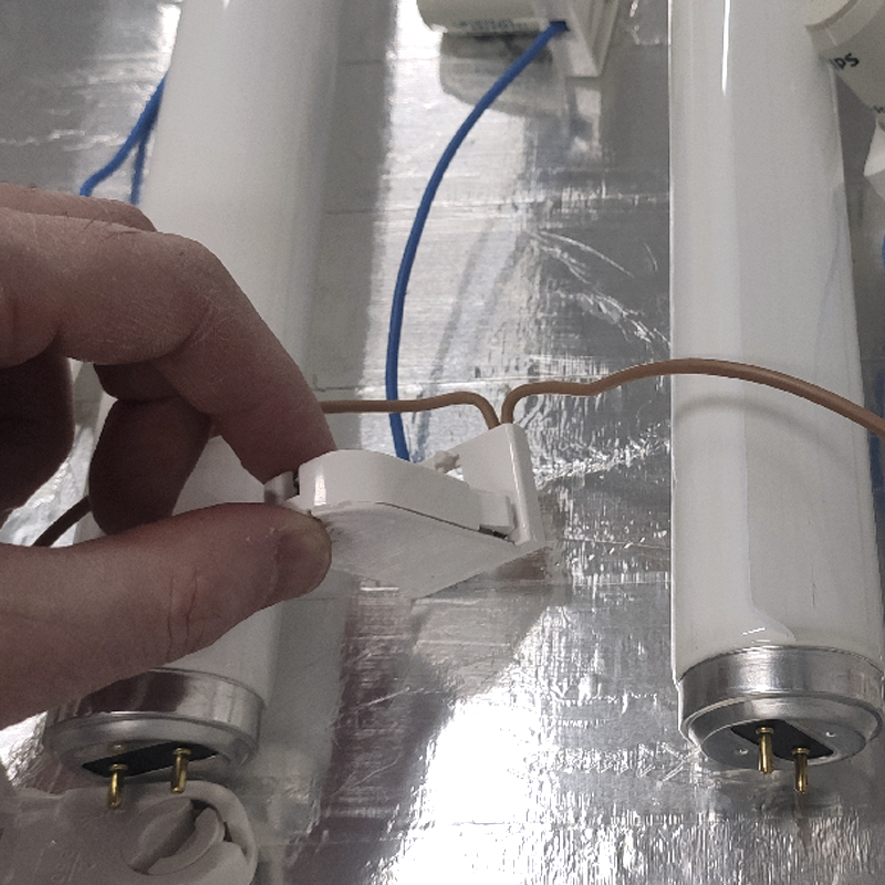
Once the distance between the fluorescent bulbs is organized, we can begin installing the bases of the bulbs. Along with the bases and depending on the space, we should also locate the place where we will place the ballasts and starters. Starters take up very little space and can always go between fluorescent bulbs. Ballasts may take up a little more space, although in this case, they have also fit between fluorescent bulbs.
We locate the elements: fluorescent bulbs, starters, and ballasts. Following the electrical diagram, we can now begin installing the cable. There is no need to fix or screw the ballasts and starters yet. This way, it is easier to manipulate the cable and make connections. To make connections, we recommend using terminal blocks and always following the manufacturer's handling advice. Making connections is not complicated, but it is important to be careful and always take the necessary precautions.
Important: With the elements located in the box, we can use only the necessary amount of cable. The colors on the cables can help us organize the splices and connections better. When handling electrical cables and connections, we must ensure that we are not connected to the power supply, avoiding unnecessary risks.
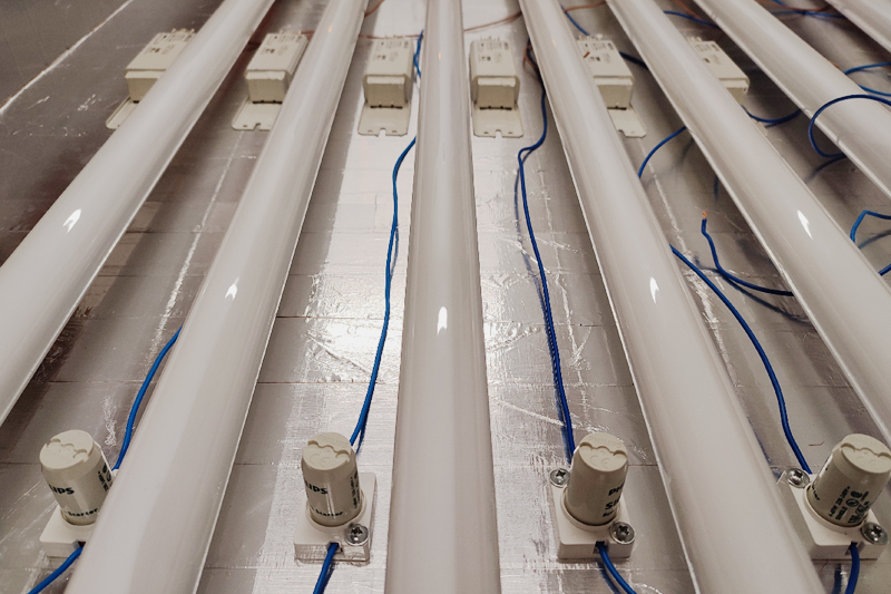
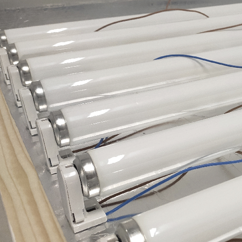
Step 6: Fixing the fluorescent tubes and other components
As we make the connections, we can start fixing the fluorescent tubes, ballasts, and starters. Gradually, we arrange the final layout of all the elements. To fix the bases of the fluorescent tubes, starters or ballasts, we can use small screws or even some mounting adhesive. The silicone gun is a useful tool to fix these pieces.
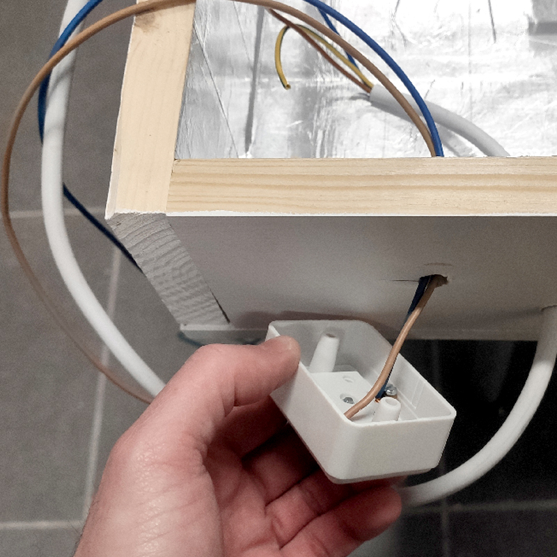
Step 7: Install a switch and tidy up the wiring
To facilitate turning on and off the UV light box, we need to install a switch. There are many different types and sizes available in the market, and we just need to follow the manufacturer's instructions to install it. The only thing left to do is to install a male plug.
Once everything is finished, we can use the same silver adhesive tape to hide and organize the cables, leaving the ends and splices visible in case we need to access the connections later. This way, everything will look cleaner and more organized.
If we have made the connections correctly, all we need to do is connect the plug to the power outlet, turn on the switch, and our UV light box is ready to use!
Important: UV light produces visible rays that tend towards violet colors and other rays below this wavelength that are not visible. However, it can cause serious eye damage. The super-actinic (UV) light should not be looked at directly. We cannot use this type of light, for example, to make a lightbox for drawing or viewing photolithographs. Directly looking at this light can damage the eyes.
Step 8: Install a timer in our UV Light Box
Once we have built our exposure UV light box, there are many ways to improve its functionalities. One of the most interesting and easy ways is to incorporate a timer to accurately control the exposure times of the UV light box.
In professional workshops, we usually work with a photocell system that counts exposures through light steps rather than time measurements. This is very functional because this system accurately controls the amount of light exposed, readjusting the wear of the exposure unit and the possible variations in the electrical network.
Despite this, the vast majority of workshops still work with exposure control systems based on time, not on the measurement of the exposed light power (steps). This is totally valid and acceptable to achieve professional jobs as long as we periodically have the constancy to perform time tests to adjust the exposure times to the wear of the lamps.
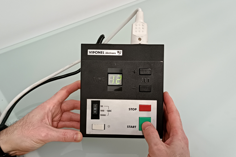
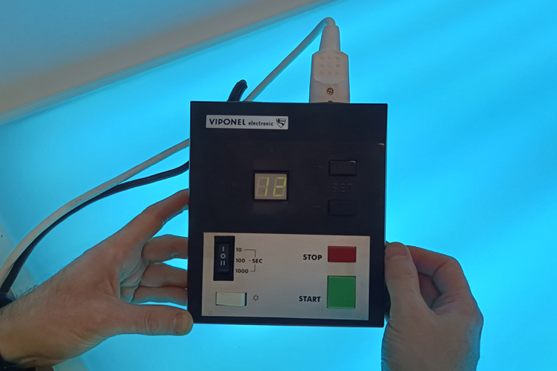
If we want to control exposure times automatically, it's as simple as installing a timer like the ones used in photography enlargers. With this type of timer, we can change and adjust exposure times, automating the work and avoiding human errors in turning on and off our UV light box.
This type of timer has a very simple usage system. The timer acts as a bridge between the current and our light box. It incorporates a plug to which we must connect our light box. We have installed a Viponel Electric timer with a digital display that allows for more precise control. In this case, the numerical control is decimal. When we use this type of controller, the light no longer activates through the switch of our light box but through the timer.
These timers can still be relatively easily found on second-hand websites or other places specialized in analog photography such as Fotoimpex (Germany). On eBay and Wallapop (Spain), many models can be found and can be good options. Using this type of controller will greatly improve the quality and performance of your homemade insolation box. It will allow you to work on other things while the exposures are carried out automatically and accurately.